Articles
Understanding Correct Earthing Test Methods for your Application
We all understand earthing system testing is important! Learn about the purpose and benefits of testing and the common tests you need to understand.
High Voltage users and operators are accountable for the reliability and safe operation of their assets, making commissioning and maintenance testing of paramount importance. While the electrical industry has a good understanding of the testing and maintenance requirements for HV equipment, earthing system testing can be a minefield of confusion. High Voltage asset users often engage external staff to ‘test’ their earthing systems and entrust in them their obligations. In this article we want to empower your staff and offer them detailed information on how the testing works, how to decipher the results, and perhaps encourage them to perform in-house testing in future.
This article will provide a brief overview of the main earthing test methods and what an earthing ‘test’ involves. The main types of investigations that can be conducted include:
- Visual inspection
- Continuity testing
- Soil resistivity testing
- Loop impedance testing
- Three-point resistance testing
- Injection testing
The issue with testing is that users need to understand the data that is collected. What is the objective of this test? How can we use this data to make appropriate decisions about safety compliance and earthing maintenance?
At the conclusion of this article, readers will have a better understanding of which test to use in each situation and will be better equipped to prevent poor test information and subsequent decision making. Staff will feel confident to define and specify their requirements, and to assess the suitability, reliability and value in testing performed internally or by service providers.
Visual Inspection
Simple and effective visual inspection is underrated and extremely beneficial in assessing condition and changes to the earthing system. It involves checks for the presence (anti-theft), redundancy, suitability and observable condition of earthing conductors, appropriate connections, surface layer material adequacy, and connected equipment adequacy. Visual Inspection is typically recommended at intervals of between 1 and 3 years and only requires minimal experience.
Integrity or Continuity Test
Integrity testing, which involves testing of electrical resistive (d.c.) continuity is one of the best indicators of the physical condition of the earthing system. It is used to measure whether items that should be connected to the earthing system are effectively bonded, and can quickly identify such problems as corroded connections, loose bolts, broken conductors, inadvertent connections, or unintentional separations.
Adequate bonding is essential to ensure that personnel are working only on equipment that is effectively connected to the earthing system. The test measures the small (micro/milliohm) resistances between items of plant and the main earth grid by passing a safe current and measuring the resulting voltage. A common question is what resistance is necessary or indicates a pass. It is interesting to note that a typical stick of dynamite will release around a megajoule of energy – this is the same in terms of heat energy generated during a 10kA fault flowing through a 10mΩ joint for a second. This highlights the need for earthing joints to be proven to be a very low milliohm resistance.
Recent developments in continuity instrumentation have meant four wire test methods have extended the range and application to make possible milliohm precision measurements across hundreds of metres distances. Applications have included inner city train station construction developments between stations and proving rail track/track slab continuity. Diagnostically, continuity testing across large structures can be used to fault find and understand where required building separations are, or are not, being achieved for electrolysis mitigation.
With the right instrument, knowledge and training, continuity testing is relatively straightforward yet very powerful, and is typically recommended at intervals of between 1 and 3 years for major substations. Some training and experience is desirable.
Soil Resistivity Testing
This testing measures the resistivity of the soil in which the earth grid is (or is to be) buried. Soil resistivity, along with soil layering, has a direct relationship to the resistance of the earth grid and therefore is very important during the design stage. Soil resistivity also forms part of the touch or step voltage hazard circuit and is important for the derivation of safety targets.
There are several test methods, of which the most commonly used is the Wenner method. In this test, four temporary electrodes are placed in a line with equal spacing. A specialised test instrument passes current between the outer electrodes and measures the resultant voltage between the inner electrodes. Analysis converts the measured resistance into resistivity dependent on the electrode spacing.
Modern test equipment makes this test relatively straightforward, but results can be significantly affected by induction, external infrastructure, electrode depth and contact resistance, and poor test practices. Therefore, a good understanding and assessment of results during the test is essential. Soil resistivity testing should be performed during the design stage, or if there is any uncertainty about existing soil models. Training and experience are known to produce better outcomes and results.
Loop Impedance Testing
This test uses a modern ‘clamp-on’ or ‘tong’ meter to test the impedance of a circuit through available earth loops. A typical application is where an electrode is also connected (via an accessible cable) to another electrode or buried earthing element. The meter is clamped around the interconnecting cable, and applies an EMF to the cable, simultaneously measuring the induced current in the cable. This provides a measurement of the impedance of the series circuit loop. This test measures the resistance/impedance of the entire circuit, not just the earth grid or electrode under test.

Whilst accuracy must be considered in the context of the circuit being measured, the test is very fast and inexpensive and can be an excellent indicator of problems, changes, or damage, when results are tracked over time. Don’t fall foul of the misconception that very low resistance large systems can be accurately measured, as the intent of the instrument is to indicate a low impedance loop does in fact exist, or an electrode or set of electrodes achieve a target resistance greater than an ohm or so.
Three Point Testing
The three point test can be performed using the soil resistivity instrument and is really only reserved for simple standalone installations and not large interconnected systems. The test involves connecting one pair of the voltage and current terminals of the instrument to the electrode under test, the other current terminal connected to an electrode placed at a known distance away, and the other voltage terminal connected to an electrode placed at around 62% of the current electrode’s distance. Test current circulated creating a voltage rise on the subject electrode with the voltage rise simultaneously measured, and the resistance reported by the instrument. This test is fast and simple but really should only be used for subject electrode resistances above an ohm or so. Other similar techniques include the slope method or voltage contour method used to improve the validity of the measurement result. Some training and experience deploying this test method is recommended.
Current Injection Testing
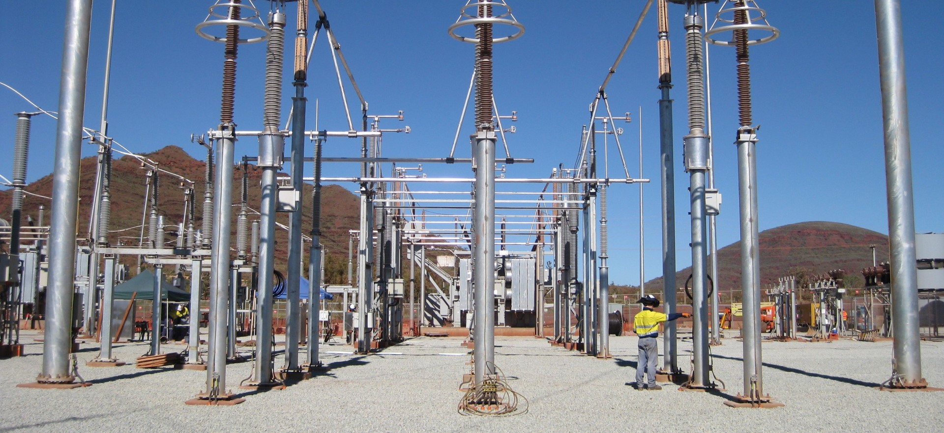
Injection testing is the most informative way of testing earthing system performance and safety. It aims to assess the actual performance of the earthing system by simulating a real fault at scaled values and measuring the effects. The effects are made measurable, even on live systems, by injecting at a frequency away from power system frequency and using frequency-tuneable instrumentation to measure currents and voltages. The test is referred to as a Low Current, Off Power Frequency Injection Test. The test current, commonly between 2 and 20 amps, causes an Earth Potential Rise (EPR) at the earth grid under test, where the voltage of the soil at the earth grid rises with respect to the surrounding area.
While test current is flowing in the fault circuit, measurements of actual touch and step voltages can be made, including where current flows during faults. Also, hazards produced on other infrastructure such as telecommunications networks or pipelines can be measured. Selection of measurement locations requires careful consideration of typical contact scenarios, transfer mechanisms and capacitive and inductive effects as it is rarely possible nor valuable to measure every impacted location.
Current injection testing is the best test to measure actual performance, but it can be complex and time consuming. It is mandated at commissioning of major substations, at intervals of between 10 and 15 years, or when there are major changes to the power or earthing system or nearby infrastructure. Significant training and experience, and equipment familiarisation is necessary to ensure the test proceeds without creating hazards for the test team or the public and avoiding testing errors as much as possible.
By Safearth – Expert Earthing Designers and Developers of Test Equipment
For more information: enquiries@safearth.com or 1800 327 844