Articles
The Evolution of Distribution Earthing Design
The last two decades has been an interesting journey for the distribution earthing designer. Not so long ago all the earthing designer was required to achieve was a simple target local earthing resistance. Popular values were 1 Ohm or 10 Ohms, or possibly 15 or 30 Ohms, depending on what was being earthed, however that changed for several reasons.
Electric shocks incidents involving people in their homes due to faults on HV distribution assets in the neighbourhood reminded engineers of the risk to the public from these assets. Concerns about these risks, whilst valid, were tempered by the realisation that electricity is an established utility. The public, including you and me, all take for granted the ongoing supply of electrical energy. So, some Australian earthing engineers teamed up to understand how to do earthing design better. Now the world is listening to Australia on this subject.
The designer of distribution earthing systems has a problem. How to determine a ‘safe’ and affordable design within a quite limited design budget? And this begs the question what constitutes a ‘safe’ design?
The last two decades have seen a lot of work done to answer the question “What constitutes a ‘safe’ earthing system”. As those close to this area know, it’s more a question of reducing risks to acceptably low levels in accord with current best practices and to as low as reasonably practicable. Rather than designs being assessed with a binary outcome, i.e., either ‘satisfactory’ or ‘unsatisfactory’, best practice suggests that ‘safe’ is no longer the right approach. The ENA Power System Earthing Guide (EG-0) Part 1 Management Principles documented how earthing risks could be quantified and an approach for completing designs using quantitative risk assessment. Recently revised Australian Standards such as AS2067, AS4853 and AS7000 now also follow this approach. Earthing designs are now approached through the lens of reducing risk levels through the transition from unacceptable to negligible risk.
And so, the world has changed for earthing designers! They now need to understand the variables relevant to quantifying the risk associated with people in shock situations. Key questions these standards raise, and address are:
- What magnitude of current through the heart will be lethal?
- What other variables affect the answer to the first question?
- If we want to quantify the risk, how do we do that?
These questions lead the earthing designer to recognise that there are a lot of variables to be considered to assess the risks associated with earthing system design properly.
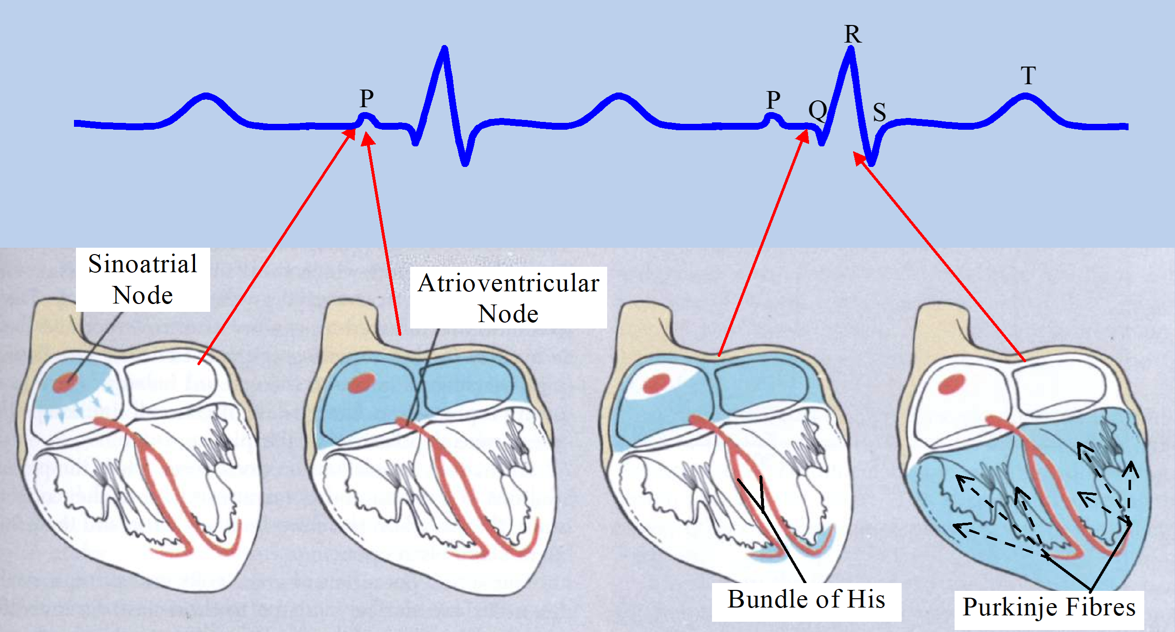
It’s not enough to understand current flow in conductors and the earth, they must understand the impact of electric current on people. The human heart is not only sensitive to the magnitude of current through it, but also to the duration of that current. If the normal functioning of heart muscle cells is interrupted by sufficient current at the wrong part of the heart cycle, then the probability of ventricular fibrillation increases dramatically. This understanding helps the designer appreciate the value of fast fault clearing times, which is reflected in the applicable safety criteria. So, a local fuse that will clear a fault in less than 0.2s may mean a simple cost-effective local earthing system will comply with the requirements of relevant Australian standard touch voltage criteria. If, however it takes upstream protection over 1s to clear an earth fault, designing a compliant earthing system may be a very difficult task indeed.
Other variables the designer must consider include:
- What exposure people will have to the asset?
- How often faults are likely to occur?
- Are the standard criteria applicable in the case under design?
- Is the resistivity of the soil higher or lower than the standard ‘safety’ curves are based on?
- What is the input impedance of the earthing system?
- What elements constitute the earthing system?
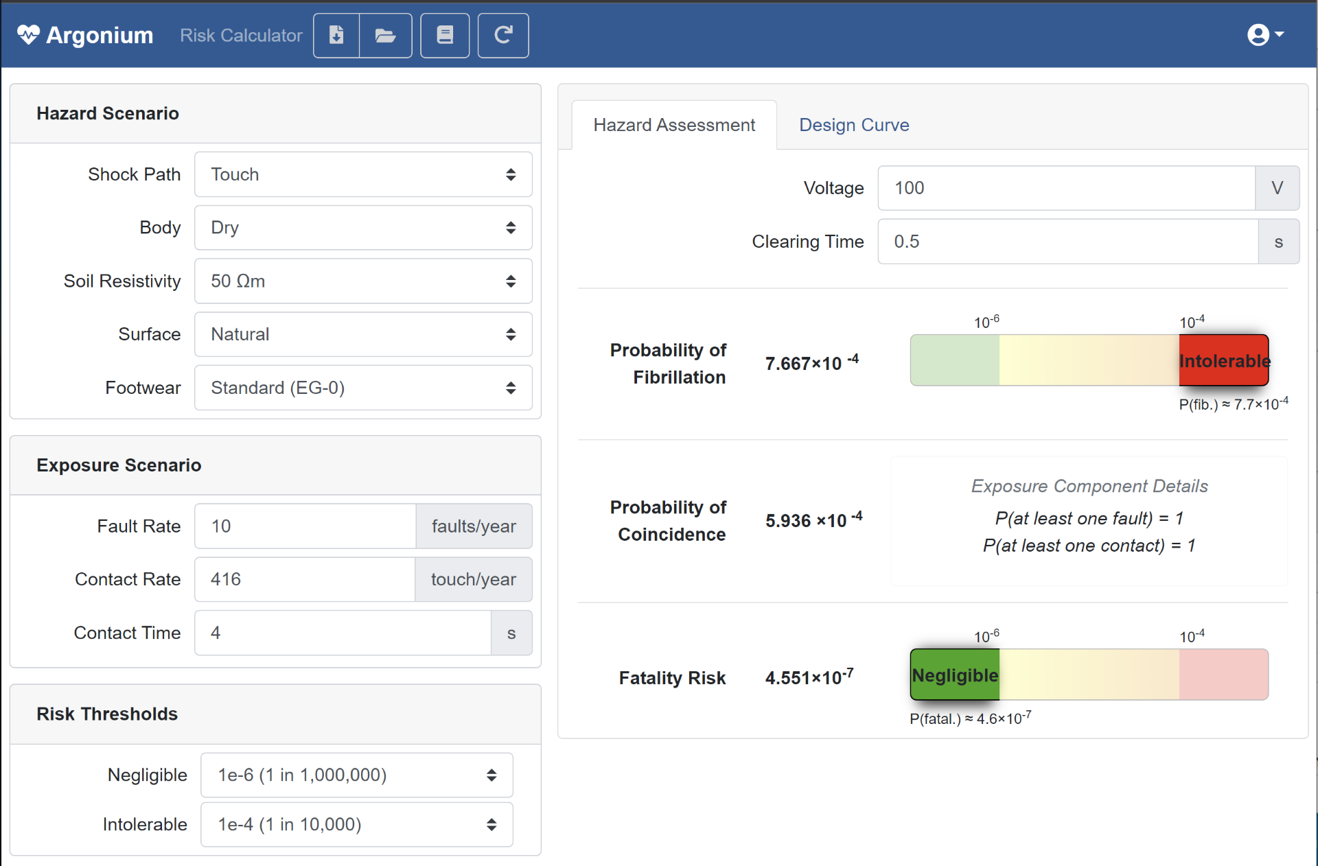
The developers of EG-0 realised, as should the reader, that calculating the risk associated with earthing system designs was complicated. To ease the transition from simple resistance targets to risk based earthing system design, the EG-0 committee had appropriate risk calculators developed to help designers assess the relevant variables and come up with a suitable prospective touch voltage curve. These calculators assess the probability of fibrillation and combine that with the probability of someone being present at the time of a fault occurring. Experienced earthing designers will be familiar with the Argon and Argonium calculators.

So, having determined suitable voltage criteria based on the environment in which the distribution asset will be installed, the earthing designer now compares these limits with calculated exposure voltages as the design evolves. Here the questions faced are:
- What elements will carry earth fault current and how will it be shared?
- What voltage will be transferred via the LV neutral into homes or businesses?
- What voltage will be transferred to other third-party assets via the soil?
- How much separation in soil should there be between these assets and the HV earthing system of the asset being designed?
- Do I need to do an earthing design for other assets other than just distribution substations?
Many earthing designers have taken short-cuts over the years because there is simply not enough budget or resources available to answer all these questions satisfactorily.
Preparing a distribution earthing design typically involves the following steps:
- Gathering Relevant Data, including:
- soil resistivity model(s),
- earthing interconnections (cable screens, LV neutrals, OHEWs, etc),
- the extent of a connected MEN network,
- prospective and actual earth fault levels and clearing times (protection elements),
- line to ground voltage,
- zone substation grid impedance, and
- selection of appropriate touch voltage criteria.
- Modelling to verify the earthing system will provide minimal risk, acceptable cost and is practical to install! Sometimes modelling will need to assess what earthing configuration is most effective, usually a choice between common bonded or separated earthing.
- If compliance cannot be achieved, what other risk mitigation measures could be used?
- And of course, documenting the final design adequately.
This is why suitable earthing design software can make a huge difference to the designer. If the software prompts the designer to gather, enter, and document the appropriate inputs in an orderly way and then calculates all the required outputs and displays that information in a manner easy to understand, the designer has freedom to spend time optimising the design rather than wrestling with numerous software packages or modules, and trying to synthesise the results. This leads to better understanding, better designs, more cost-effective designs, better documentation, and greater productivity.
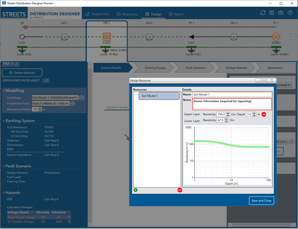
Safearth continue to develop and support a state-of-the-art distribution earthing design tool that enables an educated earthing designer to maximise their efficiency and effectiveness. This software is called STREETS Distribution Designer™. Distribution designers are encouraged to investigate if this tool could make all the difference to the productivity of their design activity (https://streets.safearth.com/). Several Distribution Network Operators (DNOs) and Accredited Service Providers (ASPs) are now using Streets® to enhance their earthing design capabilities. Some DNOs are also using Streets to define and document their CMEN or Global Earthing areas. This is another productivity improvement that Safearth can assist DNOs with. If you’d like more information on areas raised in this article, please contact us. If you’d like to learn more of the details of how to design earthing systems, our public or in-house training courses are ideal.
By Gordon McMurray – Specialist Engineer, Safearth
For more information: enquiries@safearth.com or 1800 327 844 or visit the Streets website: https://streets.safearth.com/